Computers, video games, video cameras, games computers; all of these produce video signals that must be displayed via a television set. If the TV receiver in question does not have a video input and its owner is reluctant to vandalise it in order to fit one then this sort of modulator is the obvious solution. It is a simple circuit that processes video signals to enable them to be fed straight into the TV set's aerial input.
A 'TV modulator' is really no more than a transmitter. It is a very
small transmitter, admittedly, but none the less that is what it is. What
does a modulator actually do? In general -and this design is no exception
to the rule - it is a simple oscillator that generates a frequency somewhere
in the VHF or UHF region. The oscillator is modulated with the video signal
and the modulated carrier wave thus generated is fed into the TV set's
aerial input via a cable. Then all that remains to do is tune the TV to
the correct frequency.
|
A 'TV modulator' is really no more than a transmitter. It is a very small transmitter, admittedly, but none the less that is what it is. What does a modulator actually do? In general -and this design is no exception to the rule - it is a simple oscillator that generates a frequency somewhere in the VHF or UHF region. The oscillator is modulated with the video signal and the modulated carrier wave thus generated is fed into the TV set's aerial input via a cable. Then all that remains to do is tune the TV to the correct frequency |
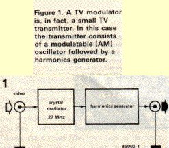 |
The block diagram of figure I shows how this is achieved. The TV modulator is made up of two parts, namely a modulatable crystal oscillator and a harmonics generator. The oscillator operates at a frequency of 27 MHz, which is quite low so inexpensive crystals are readily available. The harmonics generator converts the oscillator signal into a sort of frequency spectrum containing all the multiples of 27 MHz up to about 1800 MHz. The TV modulator's output signal is made up of a large number of little peaks, each of which is a complete transmitter signal. At least one of these will always be in band I (VHF channels 2. . . 4), one in band III (VHF channels S. . .12) and many of them will be in bands IV and V (UHF channels 21.. .69). |
The circuit diagram- figure 2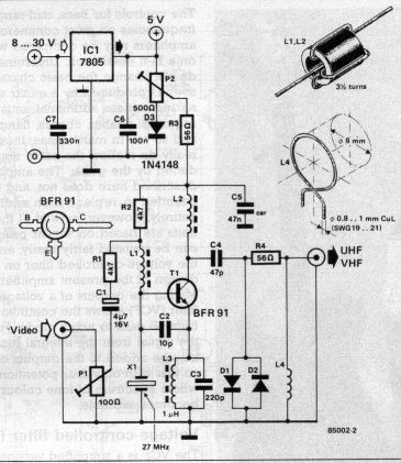 |
Parts list
Resistors:
Capacitors:
Inductors:
Semiconductors:
Miscellaneous:
*= not needed if the circuit is powered from a stabilised 5 V supply |
 |
Figure 3. Fortunately the printed circuit board for the modulator is only single-sided. The largecopper surface acts as a ground plain. |